Derivation of npn BJT emitter,base and collector currents in forward active mode
Essentially BJT is just two neighboring pn junctions put back to back.
BJT: a first pass (7.2)
In an IC npn transitor the emitter donor concentration \(N_{dE}\) is much greater than the base acceptor concentration \(N_{aB}\) which is much greater than the collector donor concentration \(N_{dC}\)
\[ N_{dE}\gg N_{aB}\gg N_{dC} \]therefore the thermal equilibrium minority carrier concentrations in the emitter, base, and collector are
\[ p_{nEo}=\frac{n^2_i}{N_{dE}}\ll n_{pBo}=\frac{n^2_i}{N_{aB}}\ll p_{nCo}=\frac{n_i^2}{N_{dC}} \]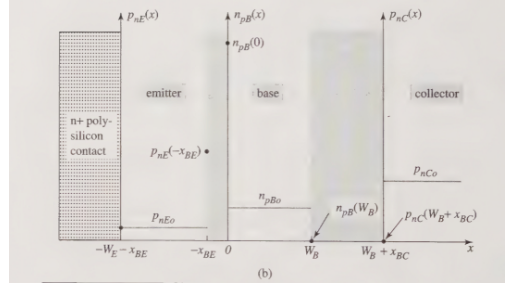
You should realize the heights of the thermal equilibrium minority carrier concentrations drawn in diagram above is a direct consequence of Fact 70. This will again will be represented in the diagram Figure fluxpath where we account for flux paths of minority carriers.
Like we have for pn junctions assuming low level injection and hence invoking law of junctions we have
\[ p_{nE}(-x_{BE})=p_{nEo}e^{V_{BE}/V_{th}}\quad n_{pB}(0)=n_{pBo}e^{V_{BE}/V_{th}} \]and
\[ n_{pB}(W_B)=n_{pBo}e^{V_{BC}/V_{th}}\quad p_{nC}(W_B+x_{BC})=p_{nCo}e^{V_{BC}/V_{th}} \]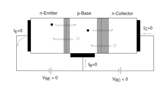
where we have for the forward active regime
- \( V_{BE}>0\Rightarrow \)
- injection of electrons from the emitter to the base
- injection of holes from the base to the emitter
- essentially the emitter base junction is forward biased
- \( V_{BC}<0 ightarrow="" ul="">
- extraction of electrons from the base to the collector
- extraction of holes from the collector to the base
- essentially the base collector junction is reversed biased
For reversed active it is basically just \(V_{BE}<0>0\) (i.e. reverse the polarity of the bias) so that the EB junction is reverse active while the BC junction is forward biased instead (which is the exact opposite of the forward active case)
Before we proceed let us analyze the currents contributions by the minority carriers.

Minority Carriers contribution to current for Reverse Active
Firstly the linear profiles and gradients should be expected knowing that the EB junction is reverse biased while the BC junction is forward biased in the reverse active mode recalling our discussion for short base steady-state pn junctions. Next, we omit the purple region entirely by treating it as zero. That is, the thermal equilibrium minority carrier concentration levels are to be treated as indistinguishable from zero. So now only considering the region above the purple region, notice that:
- The minority carrier concentration profile in the n-collector is primarily due to injection of holes from the p-base into the collector.
- The minority carrier concentration profile in the p-base is primarily due to injection of electrons from the n-collector to the base and extraction of electrons to the emitter from the base. This also explains why the extreme right side of the concentration profile in the p-base is above thermal equilibrium level (due to injection) while the left side is below (due to extraction).
- The concentration profile in the n-emitter region is similarly due to extraction of holes into the p-base. In this case, we don't have to consider it because it is in the purple region.
Now let us attempt to account for the currents. We can connect the flux stream of electrons (highlighted green) from collector to emitter contacts only. This is because recall we have assumed a short base diode. If we connect it to be the base contact, that means that recombination occurred outside the endpoints of diffusion (refers to the collector and emitter contacts). Specifically, it happened in the QNR at the base contact which is not allowed.
Next, let us connect the hole flux. Considering the direction of the hole diffusion and that the hole diffusion on the left is not considered as mentioned due to low-level injection, the above flux path highlighted in blue is the only possible path.
We will now proceed to show how the currents are now calculated, having rationalized the flux paths using the case for the forward active regime below as an example.
Minority Carriers contribution to current for Forward Active
Again the same assumptions as before apply. You should be able to rationalize the flux path indicated in Figure fluxpath for the forward active case. As usual, omitting the purple region will leave us Figure linprofileBFTforward below which we will now analyze in detail with calculations for the currents as promised.

Now again using short base diode steady state assumptions the current concentration profile will be linear like we did for the pn diode previously. In similar fashion, starting with Fick's 1st law we have
\[ J_{nB}^{diff} = q D_n \frac{d n_{pB}}{dx} \]which is by substituting our relations from law of junctions for BJT Fact 71 we have
\[ J_{nB}^{diff} = q D_n \left( \frac{n_{pB}(W_B) - n_{pB}(0)}{W_B} \right) = q D_n \frac{n_{pB0} \left( e^{V_{BC}/V_{th}} - e^{V_{BE}/V_{th}} \right)}{W_B} \]because the base collector junction is reversed biased \( n_{pB}(W_B) \) is negligible relative to the thermal equilibrium value if you recall so we may ignore the contribution by it (treat as zero as in Figure linprofileBFTforward) to obtain
\[ J_{nB}^{diff} = -\left( \frac{q D_n n_{pB0}}{W_B} \right) e^{V_{BE}/V_{th}} \]For the emitter region
\[ J_{pE}^{diff} = -q D_p \frac{d p_{nE}}{dx} \]we similarly get
\[ J_{pE}^{diff} = -q D_p \left( \frac{p_{nE}(-x_{BE}) - p_{nE}(-W_E - x_{BE})}{W_E} \right) \]and again using Fact 71 we obtain
\[ J_{pE}^{diff} = -\left( \frac{q D_p p_{nE0}}{W_E} \right) \left( e^{V_{BE}/V_{th}} - 1 \right) \]We define Electron Flux to be
\[ F_n = \frac{J_n}{-q} \]Before you proceed please recap Figure fluxpath and make sure Fact 77 makes sense to you. Then the following should be relatively straightforward as to find the respective currents from the above current densities we have found, simply multiply by the area in which the current density passes through once you have determined which diffusion flux to use.
For Base Current:
\[ I_B = -J_{pE}^{diff} A_E = \left( \frac{q D_p p_{nE0} A_E}{W_E} \right) \left( e^{V_{BE}/V_{th}} - 1 \right) \]Collector Current:
\[ I_C = -J_{nB}^{diff} A_E = \left( \frac{q D_n n_{pB0} A_E}{W_B} \right) e^{V_{BE}/V_{th}} \]Note that for the above two currents we included the negative sign because the direction of \( A \) is oriented such that it is positive into the base and the collector terminal for the base and collector currents respectively. However, observing the flux directions in Figure fluxpath (as indicated by the minority carrier movement arrows drawn) they are precisely in the direction outwards from \( A \). Note that because minority carriers are assumed to have no recombination until the ends of the diffusion at the emitter and collector contacts, the flux remains constant from the start where it originates from. That is when multiplying the flux density with the area, the area used should be the source/start of the flux. This is why we used \( A=A_E \) (emitter contact area) above.
Finally, the emitter current is just \( I_E=-(I_C+I_B) \) by Kirchhoff current law, see Figure circuitbjtforward
\[ I_E = \left( J_{nB}^{diff} + J_{pE}^{diff} \right) A_E = - \left[ \left( \frac{q D_p p_{nE0} A_E}{W_E} \right) + \left( \frac{q D_n n_{pB0} A_E}{W_B} \right) e^{V_{BE}/V_{th}} \right] \]Define Common-Base Current Gain:
\[ \alpha_F = \frac{I_C}{-I_E} = \frac{\frac{q D_n n_{pB0} A_E}{W_B}}{\frac{q D_p p_{nE0} A_E}{W_E} + \frac{q D_n n_{pB0} A_E}{W_B}} \]Simplifying our expression for \( \alpha_F \) we obtain
\[ \alpha_F = \frac{1}{1 + \frac{D_p N_{aB} W_B}{D_n N_{dE} W_E}} \]Base Current:
\[ I_B = -I_E - I_C = \frac{I_C}{\alpha_F} - I_C = I_C \left( \frac{1 - \alpha_F}{\alpha_F} \right) \]Define Current Gain:
\[ \frac{I_C}{I_B} = \left( \frac{\alpha_F}{1 - \alpha_F} \right) = \beta_F \]

Comments
Post a Comment